Don Dodson's Charger Headlights Page
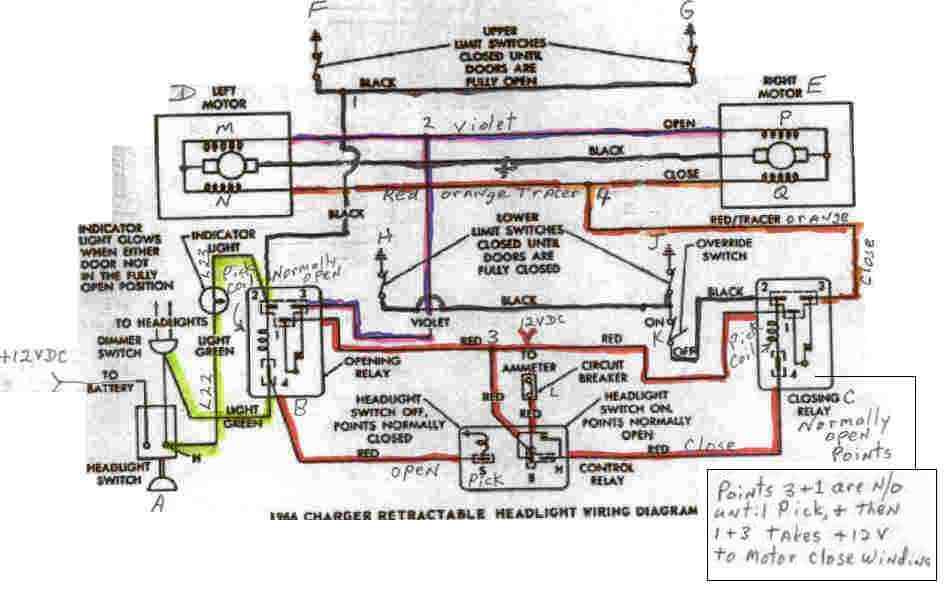
Push in on the headlight switch and the lights turn off and +12vdc is removed from the pick coil of the control relay, and the opening relay. Since the points of the control relay closes, +12vdc from the ammeter and circuit breaker goes out the right side of the control relay via a red wire to the pick coil of the close relay. If the override switch is good and is in the normal mode and not the override position, then the pick coil sees the two grounds via the lower limit switches and the closing relay activates which closes points 1 and 3 together. Now +12vdc is applied via the ammeter, circuit breaker down through the red wire to the control relay pin B, up the red wire to junction 3, over to the right via a red wire to pin 1 of the closing relay, through pin 3 and out on a red wire with and orange tracer. Plus 12vdc is applied to junction 4 of the close windings of the two motors. The motors take off and close the doors, until ground to the close relay pick coil is removed by activating the plungers of the lower limit switches. If both limit switches are good then both doors will close. If one of the switches is bad (open), then the doors will stop moving when when the one limit switch plunger is pushed in, and the other door will not be closed all the way. You now know you have a bad limit switch. It is up to you to find the bad switch.
If the override switch is defective, then the closing relay will not work and the doors will not close. It is obvious what will happen if the closing relay fails to pick, or operate correctly. The doors will not close. It is obvious what will happen if the opening relay fails to pick or operate correctly. The doors will not open, and the indicator light will stay on. However if the control relay fails to pick when we turn the lights on, we have an interesting results. Plus 12vdc is applied to both open and close windings of the motors. The open windings will see the ground and start the motors moving. Since the points are closed on the control relay, the closing relay is also activated, and +12vdc is applied to the closing windings of the motors. Both the open and close windings will now be trying to run the motor, and my guess is a burned up motor or a tripped circuit breaker. I have no idea what the symptom will be for this "what if", but I do know it ain't healthy for the motors or circuit breaker. I would unplug the headlight motors at this point, and then turn the headlights on. If you have +12vdc at pin H of the control relay, then that is a NO NO with the lights on. Check out the control relay as possibly defective.The three relays are located behind the glove box. The relay to the left is the closing relay, the relay in the middle is the control relay, and relay to the right is the open relay.
The circuit breaker is located behind kickpanel on the drivers side behind the emergency brake. There is a connector beside of the battery that will disconnect the entire grill wiring from the car, and this connector can be accessed for trouble shooting purposes. Disconnect the connector and then you can apply +12vdc to the violet wire to see if the motors will open, or you can apply +12vdc to the orange wire with the red tracer to see if the motors will close. This will let you know if the grill circuit is working correctly.
The wires from the grill circuit does not go through the three bulkhead connectors, but instead goes through a hole above the three bulkhead connectors.
Hope this helps find the problems that WILL arise with the rotating headlight wonders.
~ Don R. Dodson ~