|
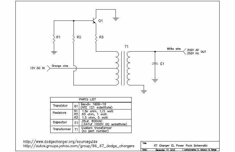
R1 is 1.5k ohms 1/2 watt R2 is 50 ohms 1 watt R3 is 1.5 ohms 5 watt C1 is the capacitor (probably worn out and the source of most troubles) The values for C1 is .047 mfd (microfarad) to .068 mfd at 600 volts AC. |
The orange wire gets +12 volts when the headlight switch is pulled out. the white wire is the output of the power pack and that white wire should be unplugged from the connector when checking the voltage on it.That white wire should have 230 volts AC on it. You will need to get a meter to check that part of the circuit. Put the negative lead on frame ground and probe the white wire with the headlight switch turned on.
The reason the plug should be unplugged is that if any gauge has a fault or short, that one gauge will kill the entire electroluminence of the gauges, which includes the needles and on a 66 I believe the clock and radio.
The power pack consists oc circuitry that makes it an oscillator that has a frequency of 250 cycles per second. It is driven by a transistor in the power pack, that beefs up the output. The output is part of the oscillator and if the output is subjected to a short in any gauge,then the oscillator will stop working and there goes the 230 volts. The test light you have will probably load down the circuit and stop the oscillator. In any case the bulb on the test light is for 12 volts DC, and you are putting it on 230 volts AC which can burn out the bulb if the oscillator keeps on running.
The El power pak is under the glove box and you will need to check the white wire output with an analog ac meter for 230 volts AC at 250 cycles per second. As long as you have around 230 volts AC the frequency will be OK. The orange wire at the power pack is where you should have +12volts dc when the headlight switch is turned on. I would disconnect the white wire plug at the power pack and check the AC voltage to see if the power pack is good. If any of the gauges has a short, then the power pack oscillator will not run, and there will be no AC voltage generated if the oscillator does not run. You will be able to isolate where the problem is if you keep this fact in mind. Might be just one gauge causing all of the gauges EL not to work.
The markings on the top only identify the transistor manufacturer as Bendix type 1859-29. The transistor is a PNP transistor and current flow is against the arrow, down through R3 resistor and then through the primary of the transformer setting up a field in the transformer that is induced into the secondary that also chargers the capacitor. This field of the transformer and the capacitor starts the oscillations that creates the frequency of 250 cycles per second. The transformer is not replaceable but the capacitor can be replaced. Just ask for a .05 micro farad 600 volt ac capacitor. Do not accept an electrolytic capacitor as they will not work. The purpose of the transistor is to excite the primary of the transformer to make it produce a more intense field thereby producing a more healthy output from the secondary of the transformer. After all you are changing 12 volts DC to 200 volts AC and something has to be there working away to make this change, and the power transistor is the dude doing the work. This is a simple circuit so anyone worth their reputation should be able to trouble shoot the circuit if yours does not work.
The orange wire is where the +12 volts is applied and this creates current flow through the T1 transformer and r2 and r3 resistors. This current flow starts the transformer T1 to develop a negative potential at the base and a positive potential at the top of T1 while developing a positive potential on the base of the transistor to shut the transistor off. This starts the oscillating effect of T1 and C1 and these oscillations cause the transistor to conduct and shut off which generates the frequency and power level of the output which is observed on the white wire out. If the white wire out is shorted to ground this would put ground on both legs of the secondary of the transformer which would stop the oscillator and the lights would go out of course. The oscillator frequency which is determined by the values of T1 and C1 and the action of Q1 (transistor) would determine the output voltage. The output is 200 volts ac, but I don't have a frequency meter to determine the frequency. I'll just leave that to the engineers who designed the thing. Very seldom do transformers give trouble, and as for the capacitor, it can not be an electrolytic type capacitor, because it is in an oscillator circuit. Resistors and transistors and capacitors can be obtained at numerous electronic places.
With a multimeter, you can check the load at the orange wire to the EL pak for instance. Say it reads 12 volts. Now you can test the pak by switching to ac test and see if you are getting the minimum of 200 acv from the white wire. Each power pak will get a slightly different read. i.e.., mine reads about 260acv.